
Why Poor LED Street Luminaire Design Creates Tender and Project Risk
A street luminaire can meet a wattage requirement and still fail the project. Incorrect illuminance targets, unsuitable pole spacing, poor optical distribution, or unverified photometric data can create dark spots, excessive glare, and non-compliant road lighting. These problems may lead to redesign, rejected samples, higher maintenance costs, and delayed project delivery. For engineers and tender specifiers, the real challenge is not simply finding a low-price Supplier. It is selecting a luminaire whose photometry, geometry, protection, documentation, and long-term performance fit the actual road.
The best LED street luminaire is selected by matching illuminance or luminance and uniformity targets with road geometry, pole height, spacing, optical distribution, and verified IES or LDT photometric data. Luxific provides Type I to Type V optical options and project-oriented technical support for this selection process.

1. Set Illuminance, Luminance and Uniformity Targets First
Do not begin with wattage. Begin with the lighting performance required by the road. Illuminance is commonly expressed in lux, while luminance considers the visual brightness of the road surface from the driver perspective. The correct target depends on road classification, traffic conditions, surrounding environment, and the applicable local standard.
Key Inputs for the Lighting Calculation
- Road width and number of lanes
- Traffic volume and road classification
- Pedestrian and cycling activity
- Intersection, crossing, curve, or conflict areas
- Required average illuminance or luminance
- Required overall and longitudinal uniformity
- Glare and light-spill limitations
- Road surface characteristics and reflectance
Luxific project information emphasizes that proper street lighting should balance brightness, coverage, safety, energy use, spacing, shielding, and local requirements. The lighting calculation should therefore define the performance target before a Manufacturer recommends a specific wattage.
| Design Parameter | What Engineers Should Check | Why It Matters |
|---|---|---|
| Illuminance | Average and minimum values in lux | Defines the amount of light reaching the road |
| Luminance | Average road-surface luminance where required | Supports driver-oriented visual evaluation |
| Uniformity | Overall and longitudinal uniformity | Reduces dark spots and uneven visual conditions |
| Glare | Optical control and fixture orientation | Helps maintain visual comfort and road safety |
2. Match Pole Height, Spacing and Arrangement to the Optics
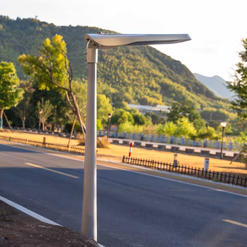
Even an efficient luminaire cannot compensate for unsuitable installation geometry. Pole height, pole spacing, roadway width, outreach, tilt angle, and mounting arrangement work together with the optical system. A luminaire that performs well at one geometry may produce poor uniformity at another.
Check the Road Geometry Before Selecting the Luminaire
- Measure the complete roadway width and lane arrangement.
- Record the proposed pole height and mounting position.
- Determine the approximate pole-to-pole spacing.
- Identify single-side, staggered, opposite-side, median, or central arrangements.
- Define the target illuminance or luminance and uniformity.
- Run the photometric calculation using the actual installation geometry.
The source material notes that spacing influences uniformity: excessive spacing can create dark areas, while unsuitable spacing can produce excessive brightness. Pole height also varies according to location, purpose, and surroundings. Therefore, spacing should be validated through calculation rather than selected only from a catalogue recommendation.
Use a Geometry-Based Selection Approach
- Wide roads may require a different optical reach than narrow urban streets.
- Higher mounting positions can require different distributions and aiming angles.
- Large spacing should be evaluated for minimum illuminance and uniformity.
- Curves and intersections should be assessed separately from typical road sections.
- Obstructions, trees, buildings, and adjacent properties should be included in the design review.
3. Select Type I to Type V Optics and Control Cutoff
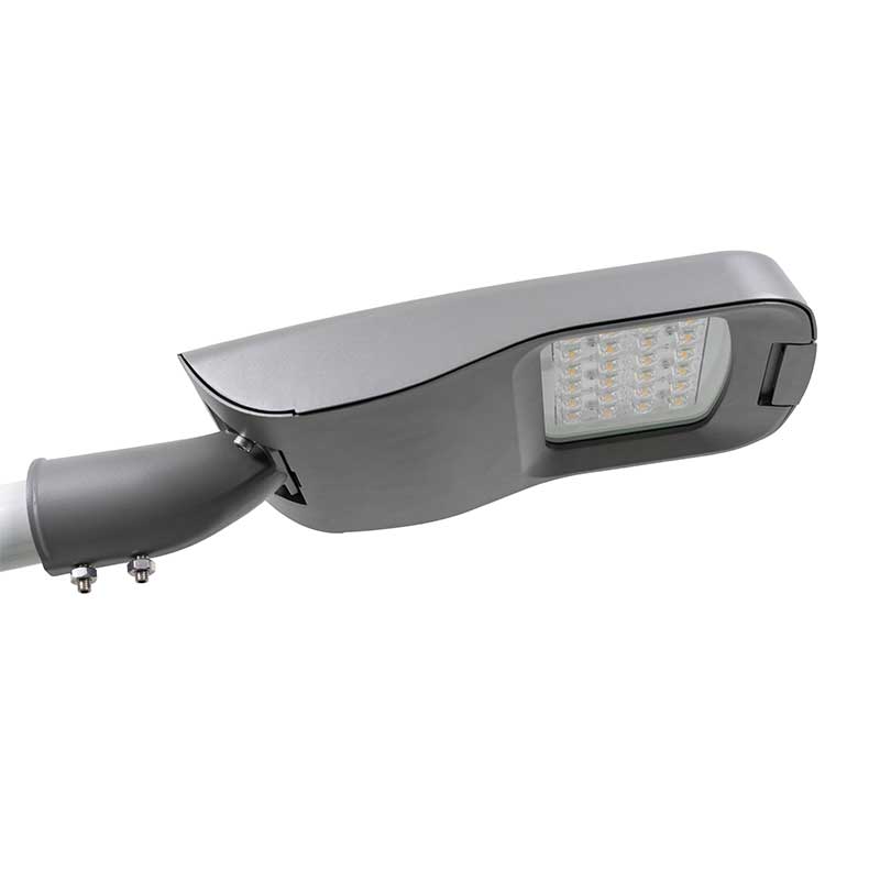
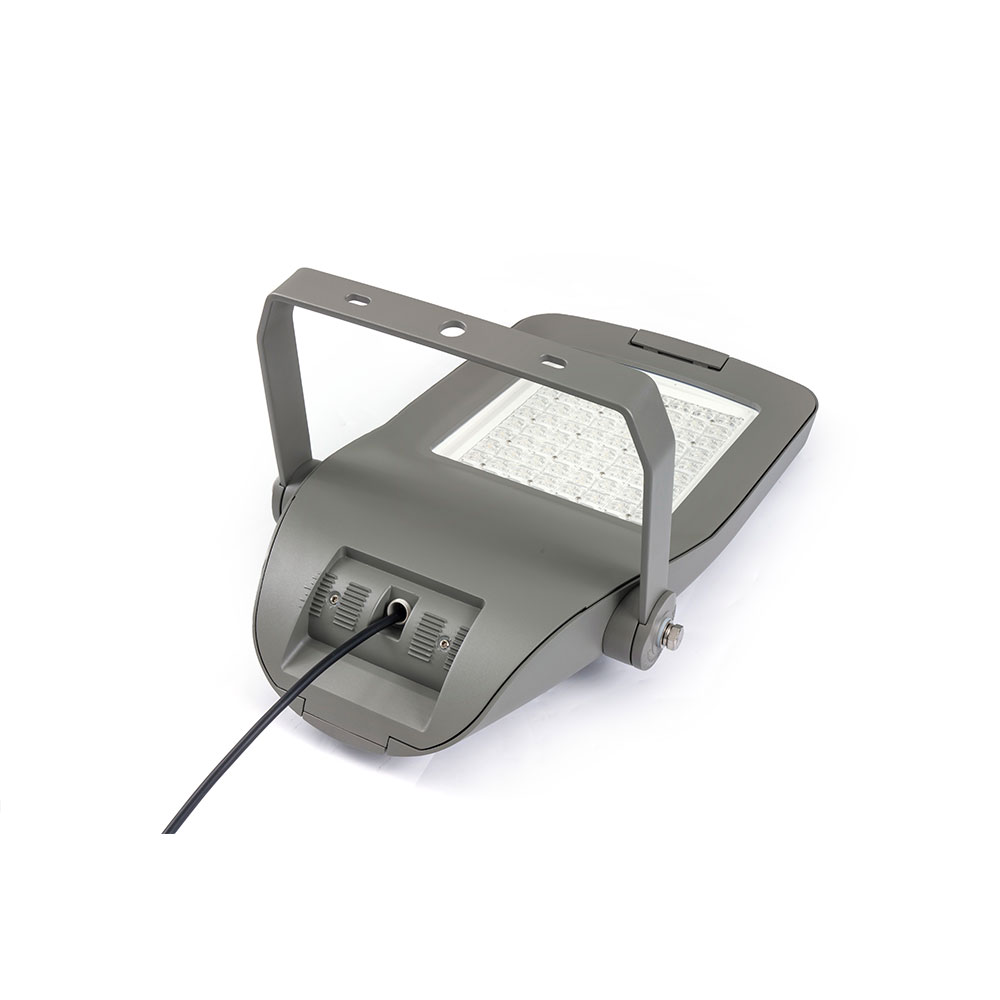
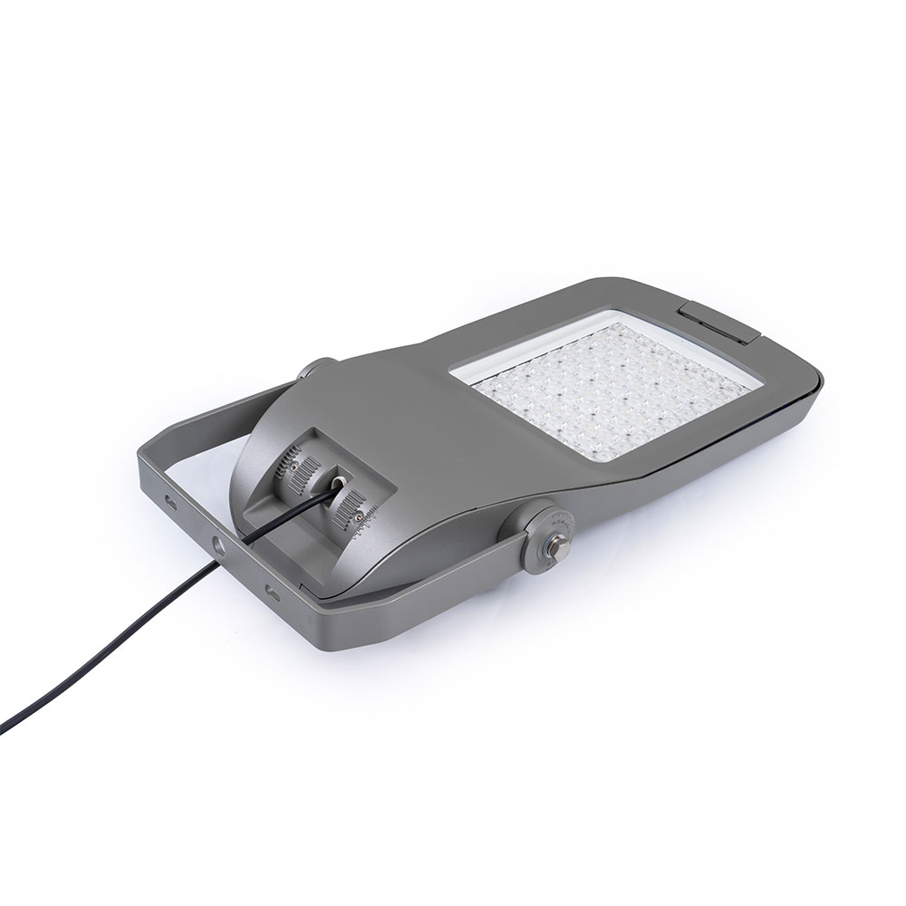
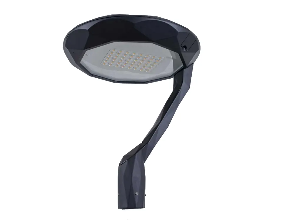
Optical distribution determines where the luminaire puts its light. Luxifics PIECES street luminaire uses a modular optical system with Type I to Type V distributions, allowing engineers to match light distribution to different road and public-area applications. The same luminaire family can therefore be configured for different project geometries rather than relying on one universal beam pattern.
How to Think About Type I to Type V Distribution
- Type I can suit narrower roadway or pathway-oriented applications where concentrated distribution is useful.
- Type II can support broader roadway layouts and is commonly considered for driveways and road edges.
- Type III can provide wider forward distribution for broader road coverage.
- Type IV is useful when stronger forward projection is needed from roadside mounting.
- Type V provides a more symmetrical distribution and can suit open-area or central-mounting applications.
These descriptions are starting points, not substitutes for photometric calculations. The final optical choice should be based on the actual pole arrangement, mounting height, road width, spacing, target performance, and local requirements.
Consider Cutoff, Glare and Light Spill
Road lighting is not only about putting enough light on the pavement. The optical system should also control unwanted light outside the intended area. Proper shielding, direction, and cutoff can reduce glare and unnecessary spill toward nearby properties or sensitive environments. Luxific documentation describes Type I to Type V optical options as supporting tailored illumination, glare reduction, and improved uniformity.
4. Validate the Design With IES or LDT Photometric Files
A tender specification should not depend only on catalogue lumen values. Photometric files allow engineers to test how the luminaire behaves within the actual road geometry. For a serious project, the Supplier should provide appropriate photometric data so the lighting designer can verify the proposed installation.
Photometric Validation Checklist
- Obtain the correct IES or LDT file for the exact luminaire configuration.
- Confirm LED power, optical distribution, mounting orientation, and other relevant parameters.
- Build the actual roadway geometry in the lighting calculation software.
- Enter pole height, spacing, arrangement, road width, and mounting position.
- Check average and minimum illuminance or luminance as applicable.
- Check overall and longitudinal uniformity.
- Review glare, spill light, and areas outside the road where relevant.
- Compare the calculated results with the tender requirements before approving the sample.
| Supplier Documentation | Engineer Verification |
|---|---|
| IES or LDT photometric file | Confirm file matches the quoted configuration |
| Optical distribution | Check Type I to Type V selection against road geometry |
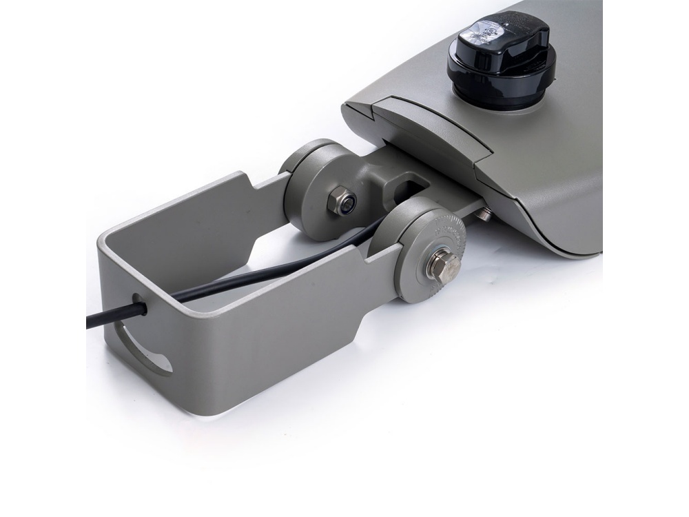
| Product dimensions and mounting data | Confirm compatibility with existing or proposed poles |
| Technical specifications | Compare power, input range and environmental ratings |
| Certification documents | Verify applicable market and project requirements |
5. Make the Luminaire Selection Project-Ready

For government, municipal, EPC, infrastructure, and public lighting projects, technical documentation can be as important as the luminaire itself. Luxific documentation for the PIECES series lists IP66 and IK09 protection, 10KV and 10KA surge protection options, multiple control inputs, and certifications including CE, CB, ENEC, EMC, TM21, LM79, and IEC 62471 for the specified configuration. Exact certification scope should always be confirmed for the target market and model.
When Customizable, OEM and ODM Options Add Value
Not every road project fits a standard catalogue configuration. A Customizable solution may be appropriate when the project requires a specific optical distribution, mounting interface, housing treatment, branding, packaging, or technical configuration. Luxific supports OEM and ODM projects with technical design, prototyping, quality control, and logistics services. This can be particularly useful for Wholesaler programs and infrastructure projects with defined tender specifications.
Final Engineering Checklist
- Road classification and application are clearly defined.
- Illuminance or luminance targets are documented.
- Uniformity requirements are established.
- Pole height and spacing are confirmed.
- Mounting arrangement and tilt are specified.
- Type I to Type V optics are evaluated against the geometry.
- IES or LDT data is available for the exact configuration.
- Glare and light spill have been considered.
- Required certifications and test reports are identified.
- Delivery schedule, warranty, maintenance, and lifecycle cost are reviewed.
Submit Your Road Data for a Project-Specific Selection
Send Luxific your road dimensions, pole height, target illuminance, quantity, required market certifications, and delivery time. Our team can evaluate the appropriate LED street luminaire, optical distribution, and project configuration for your tender or procurement plan.